Wouldn’t it be nifty if we all knew which rigs were stiff and by how much, and where the wobbliness comes from? I propose measuring flex in 3 places, even on rigs without a fuse/foil connection: on the mast right above the fuse, on the fuse, and on the foil.
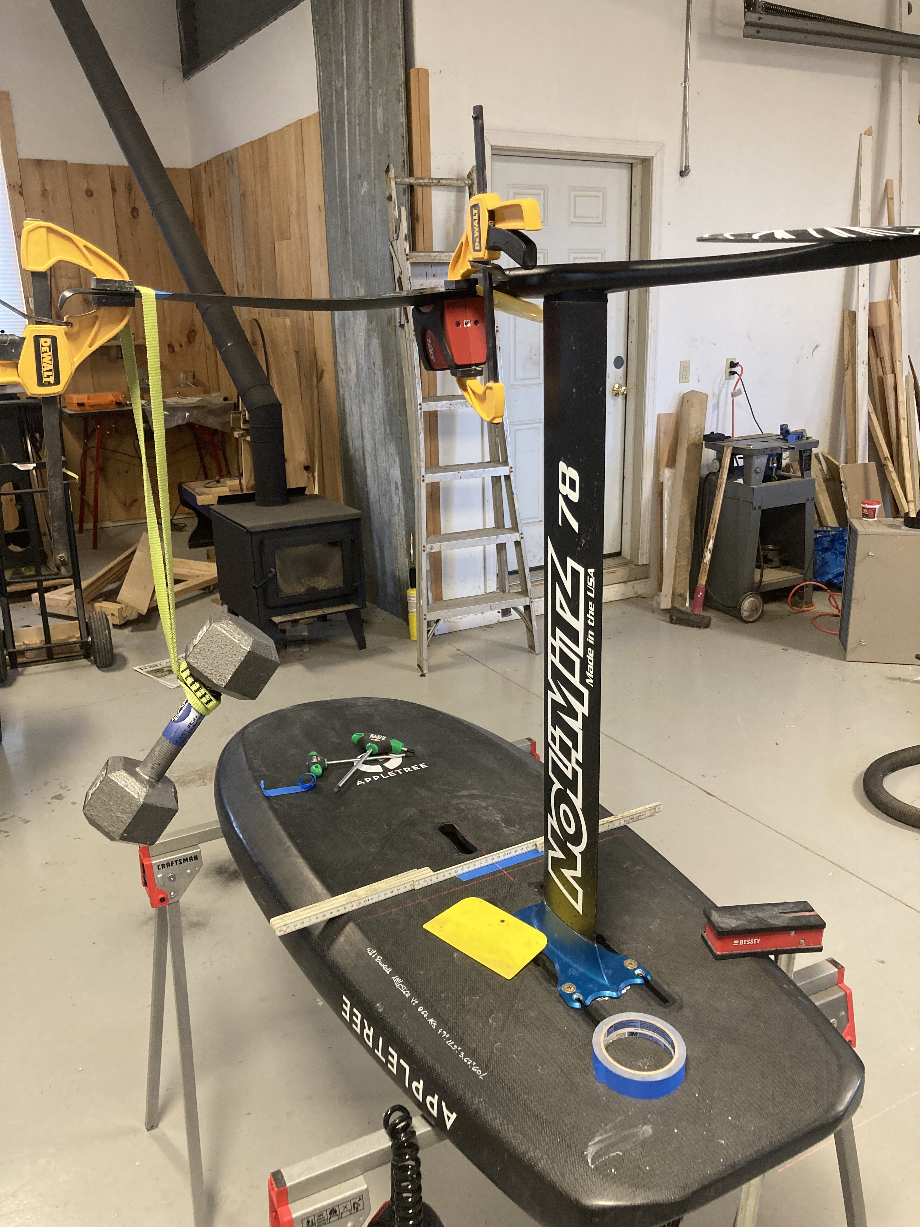
Flex shall be induced by hanging a, readily available in US, 15lb(?) weight on the foil, 400mm(?) from the center, a distance that works down to 800mm span foils. The mast should be attached to your freshest, burliest board. Tape a sheet of graph paper to the surface under the foil, with one of its lines on the centerline of the board. Before hanging the weight for each location, attach a laser to the mast, fuse, or foil, with it pointing on the centerline. After hanging the weight mark each one on the graph paper.
I’d guess that the mast would generally account for the largest space between centerline and the foil’s mark, with a little more each for the fuse and foil. But if everyone did this test the same then it would be really interesting wouldn’t it….How much stiffer is a lack of fuse/foil connection than, say Axis’s? Is it at all? Whose mast is stiffest? We’d all know! I think I’ll do this in the next few days on my hodgepodge of cedrus, NL, takuma, and axis. It would be helpful too to provide info such as, of course, what the rig is including mast length, but also your best attempt at measuring it’s thickness, how fresh the setup is and how much salt is built up, and anything else that seems relevant.
~70cm cedrus with axis 910b
Almost no difference btwn mast and fuse, moderate salt buildup on fuse
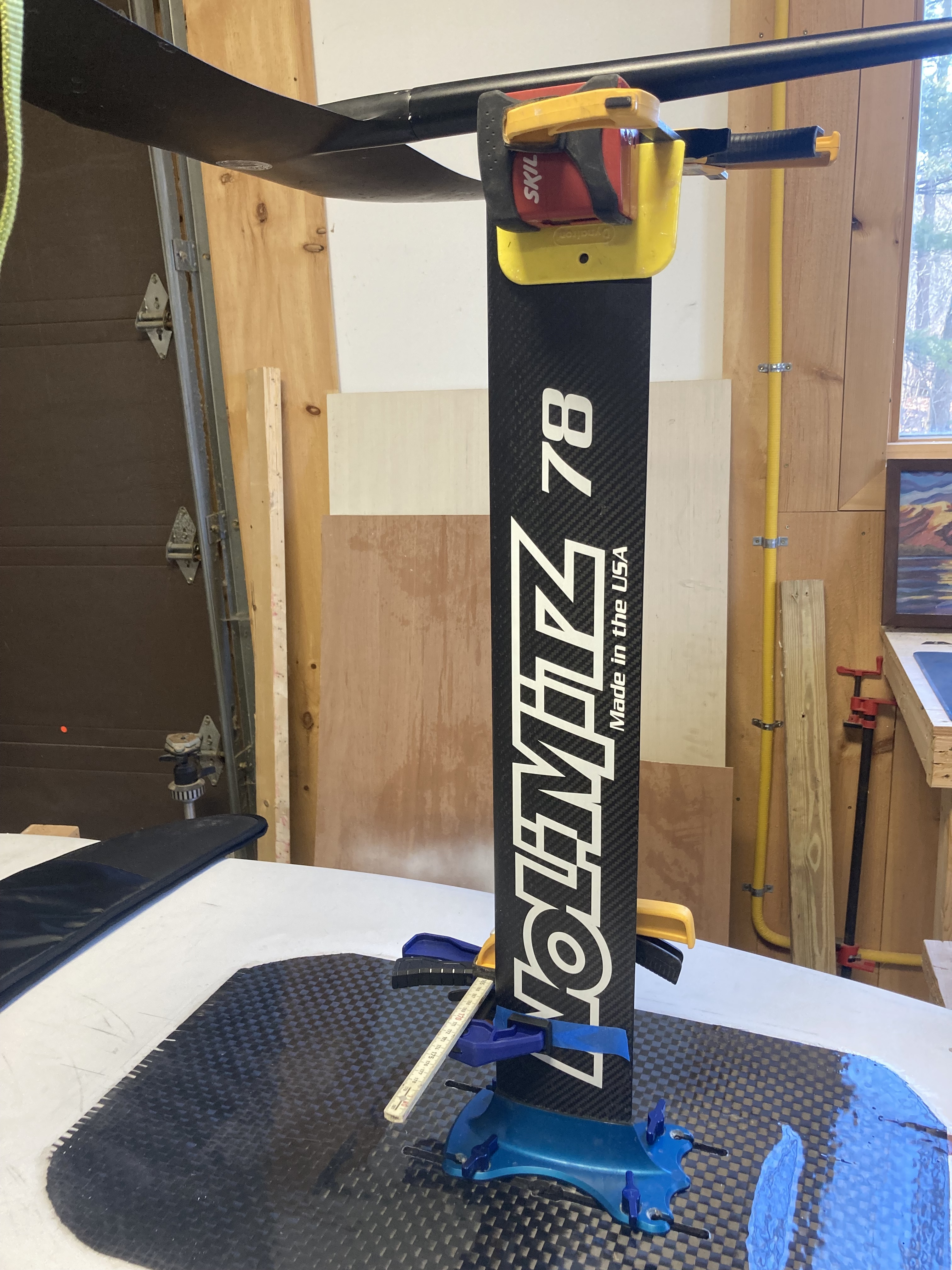
78cm No Limitz with 1095
Inside of foil foil-taped so fits hand tight with no real wobble.
Notes:
both fuse/foil joints showed very similar flex.
I attached the laser as close to the fuse as possible on the foil
On the takuma i couldn’t attach to the round fuse so attached to the tail instead.
Use one side of laser line or another, but remember which side. When shimming the laser, I found it easier to shim too much, then pull it out until in the line.
I had to put a clamp on the foil at 400mm, so center the laser with it on.
Fuse/foil:
Both black axis and shimmed m6 takuma: 6mm I think that is fascinating.
Query: is most of that flex a result of the fuse twisting? If so, would no joint make a difference, or what about carbon? Probably very dependent on laminate schedule of individual brand fuse. What about axis regulator vs advanced? Less distance from mast to foil goes farther than connection for stiffer rig?
I would propose that the test weight is higher than 15 lbs. something more like 30lbs at 1 ft. Ideally even higher. Some flex issues only become apparent at real loads.
I can see that, and I’ve since noticed that 380mm and 15” are close together, and just looked it up and 20#=9.07kg, so those could be the standard, nobody has to find an odd tape measure, and the hardest thing might be making a 9kg weight.
I would be pretty wary of ending up measuring foil box flex with that setup? If you could come up with a clearer spec I’ll do my best to replicate it perhaps even on the same Axis setup and we can compare.
I mistakenly read your message as 20 lbs not 30, but I played with different distances out the foil, and it really makes a difference how far out you go, so I’d guess 20 at 15” is at least 30 at 12”? And if your foil is less than 30” total you can extend it with a board or something, since it only matters how the base of it moves. IDK, might be nice to have compatible units.
Edit: since euros etc have to make a weird size weight anyway let’s to 30lbs at 15”/380mm.
The only way I can think of to isolate that is to connect some point on the foil to the base with a block and tackle and a load cell. I don’t have one of the latter. Oh, then how’d you measure the flex at each point? Maybe everyone needs to buy an Appletree!
Edit: you’d attach something to the base of the mast for the laser to hit. It’d be cool if someone did that.
Edit 2: you’d have to do some trigonometry to account for the angle of pull vs a weight.
I did my gofoil setup a while back on the centerline axis and it was interesing. Load testing my prone setup (standupzone.com) My goal was to replicate foiling loads which at my weight is scarry. I wouldn’t attempt this with regular gear. Very stressful. Doing wing loading like your talking about will be much smaller loads seems more reasonable.
I think with alot of these brands quality control and production variance is the real issue. There’s alot of luck wether your parts are going to fit tight or not and even layups are inconsistent (I just found dry laminate inside a busted 1095!)
Unless you drill into concrete there’d be flex in a floor too. But if you attach something directly to the mast for the laser to hit right under/above the base, you’d isolate that connection.
30 pounds should be fine and make it easier to see subtle differences. 15 pounds didn’t move the axis mast fuse at all.
I’m always pushing and prodding my foil, feeling for flex and movement to just assess before a sesh. Lots of people are really put off by it, tell me I’m gonna break it that way. But the forces of actual riding are immense. 220 lbs going through it just riding straight and flat. Imagine a breached tip on a hard banked turn with extra g forces in addition. I think 100lbs at 1 foot from center would even be reasonable!
This is all very exciting. A question for an engineer: does the rate of acceleration of the force on part of the wing make a different for the deflection? And also how does the rebound movement back to unloaded state effect the flying characteristics ?
What I’m trying to get at, is I think there are some rigs on the market that might score very “well” on the test you are coming up with, but might fly like shit in the water due to the more dynamic nature of accelerating non linear loading while turning and controlling through turbulence etc.
I guess we’ll see, I’ll lend you my setups for testing for sure will be neat to see the results.
I did what I am calling the standard test for now: 30# 15” out the foil measured 26” from the fuse on the mast. Some interesting results, one new test is I measured the fuse (Axis black regular only because the square shape made it easier) at the mast AND right behind the foil. About a third of the flex “in the foil connection” came from the fuse twisting. And M6 takuma beat Axis at that measurement, which I would not have guessed, IDK if my foil-tape job is why? Anyway spreadsheet below, if you do the test please plug in numbers. It would be cool to get enough to make graphs. Nerd Alert!
Yes, I love to borrow when I can….I’d love to test a carbon lift fuse for twist.
So something i noticed with my Gong V2 carbon mast is that it twists when subjected to a bending load. Not very surpising given the fore and aft assymetry in the section shape; unlike with isotropic alu masts, having anisotropic carbon masts bend without and twist would require some very careful tweaking of the layup schedule to achieve.
Think this standardized test is a great idea, probably need to find a way to account for this twisting effect fornit to be generally applicable.
This tests the transverse moment capacity of the mast - and for tapered carbon masts especially this will largely be driven by the lower mast section. I like to do the following tests also:
side load at tip of mast, no torsion. Mast bolted to bench etc, load applied at tip. Total side deflection measured - this gives good indication of absolute stiffness of mast to side loads, and especially stiffness of upper mast will be driver.
torsional moment - mast bolted to bench etc, load applied to tip of fuselage on mast, twist measured on mast. This gives indication of overall torsional stiffness of mast